Runs your sketch
Arduino
Brain
Loading part…
edge detection and toggle latch
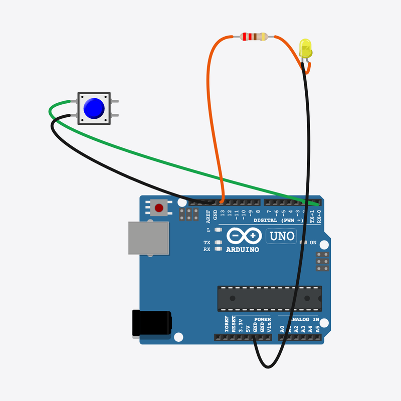
Each button press toggles an LED on or off using edge detection.
Pin connections
| Part 1 | Part 2 | |
|---|---|---|
Arduino pin 2 | → | Button pin 1 |
Button pin 2 | → | Arduino GND |
Arduino pin 13 | → | Resistor pin 1 |
Resistor pin 2 | → | LED anode (+) |
LED cathode (-) | → | Arduino GND |
One press, flip the state!
Detect the moment of press (edge) to toggle the LED on or off.
Power buttons on devices often toggle with edge detection.
The problem
Holding a button on is not a toggle — you need to catch the press instant.
Think of it like
Like flipping a coin once per tap — not while your finger rests.
Runs your sketch
Arduino
Brain
Each press toggles state
Button
Input
Protects the LED
Resistor
Safety
Stays on until next press
LED
Output
Remember last reading
We compare today’s reading with lastReading to spot a change.
bool reading = digitalRead(BUTTON_PIN);
Detect press edge
HIGH→LOW means the button was just pressed — one edge, one toggle.
if (lastReading == HIGH && reading == LOW)
Flip stored state
ledOn latches the LED state between presses.
ledOn = !ledOn;
digitalWrite(LED_PIN, ledOn ? HIGH : LOW);
Then loop back to step 1
Follow these steps in order. Match the wires to the colors shown.
Place Arduino
Place the Arduino (uno) on the breadboard.
Arduino placed!
Place Button
Place the Button (btn1) on the breadboard.
Place Resistor
Place the Resistor (r1) on the breadboard.
Place LED
Place the LED (led1) on the breadboard.
Connect Arduino pin 2 to Button (btn1) 1.l
Connect Arduino pin 2 to Button (btn1) 1.l.
Connect Button (btn1) 2.l to Arduino GND
Connect Button (btn1) 2.l to Arduino GND.
Connect Arduino pin 13 to Resistor (r1) 1
Connect Arduino pin 13 to Resistor (r1) 1.
Connect Resistor (r1) 2 to LED (led1) anode (+)
Connect Resistor (r1) 2 to LED (led1) anode (+).
Connect LED (led1) cathode (-) to Arduino GND
Connect LED (led1) cathode (-) to Arduino GND.
Toggle state variables
bool ledOn = false;
bool lastReading = HIGH;
ledOn remembers the LED; lastReading remembers the previous button read.
Edge detection
void loop() {
  bool reading = digitalRead(BUTTON_PIN);
  if (lastReading == HIGH && reading == LOW) {
    ledOn = !ledOn;
    digitalWrite(LED_PIN, ledOn ? HIGH : LOW);
  }
  lastReading = reading;
  delay(10);
}
Only on a fresh press does the LED flip — holding the button does nothing extra.
const int BUTTON_PIN = 2;
const int LED_PIN = 13;
bool ledOn = false;
bool lastReading = HIGH;
void setup() {
  pinMode(BUTTON_PIN, INPUT_PULLUP);
  pinMode(LED_PIN, OUTPUT);
  digitalWrite(LED_PIN, LOW);
}
void loop() {
  bool reading = digitalRead(BUTTON_PIN);
  if (lastReading == HIGH && reading == LOW) {
    ledOn = !ledOn;
    digitalWrite(LED_PIN, ledOn ? HIGH : LOW);
  }
  lastReading = reading;
  delay(10);
}
Q1. Where does repeating work belong?
Q2. Why check lastReading == HIGH && reading == LOW?
Make edge checks snappier — change delay(10) to delay(5).
Hint: Last line of loop().
Comment the line ledOn = !ledOn explaining “flip state”.
Hint: Line 13.
A line-by-line tour of the sketch — the same steps as in Robo Gurukul Studio.
Program overview
Technical
Sketches have globals, then setup() once, then loop() forever.
In this project
Each button press toggles an LED on or off using edge detection.
Why here
Read from top to bottom. Hover words or lines for help!
const int BUTTON_PIN = 2;
const int LED_PIN = 13;
bool ledOn = false;
bool lastReading = HIGH;
setup()
Technical
Runs one time when the board turns on.
In this project
Sets up pins and libraries for Toggle Button.
Why here
One-time setup belongs here—not in loop().
void setup() {
  pinMode(BUTTON_PIN, INPUT_PULLUP);
  pinMode(LED_PIN, OUTPUT);
  digitalWrite(LED_PIN, LOW);
}
loop()
Technical
Runs again and again after setup() is done.
In this project
This is the main action you see in Toggle Button.
Why here
Repeating work (blink, read sensors) goes here.
void loop() {
  bool reading = digitalRead(BUTTON_PIN);
  if (lastReading == HIGH && reading == LOW) {
    ledOn = !ledOn;
    digitalWrite(LED_PIN, ledOn ? HIGH : LOW);
  }
  lastReading = reading;
  delay(10);
}
Try this: Change numbers in loop(), then compile and run the simulator.
pinMode
Technical
Tells a pin if it listens or drives something.
In this project
Gets the Toggle Button circuit ready in the simulator.
Why here
Goes in setup() because we only set pins once at the start.
pinMode(BUTTON_PIN, INPUT_PULLUP);
digitalWrite
Technical
Turns a pin ON or OFF.
In this project
Controls lights, motors, or buzzers in Toggle Button.
Why here
Goes in loop() so it can keep changing while the program runs.
digitalWrite(LED_PIN, LOW);
digitalRead
Technical
Checks if a pin is ON or OFF.
In this project
Reads buttons or sensors in Toggle Button.
Why here
Goes in loop() so we can react when something changes.
bool reading = digitalRead(BUTTON_PIN);
delay
Technical
Waits for some time. Nothing else runs during the wait.
In this project
Controls speed so you can see Toggle Button in the simulator.
Why here
Right after an action that should stay the same for a moment.
delay(10);