Runs your sketch
Arduino
Brain
Loading part…
multiple inputs and first-wins logic
Two players race — first button press wins and locks out the other.
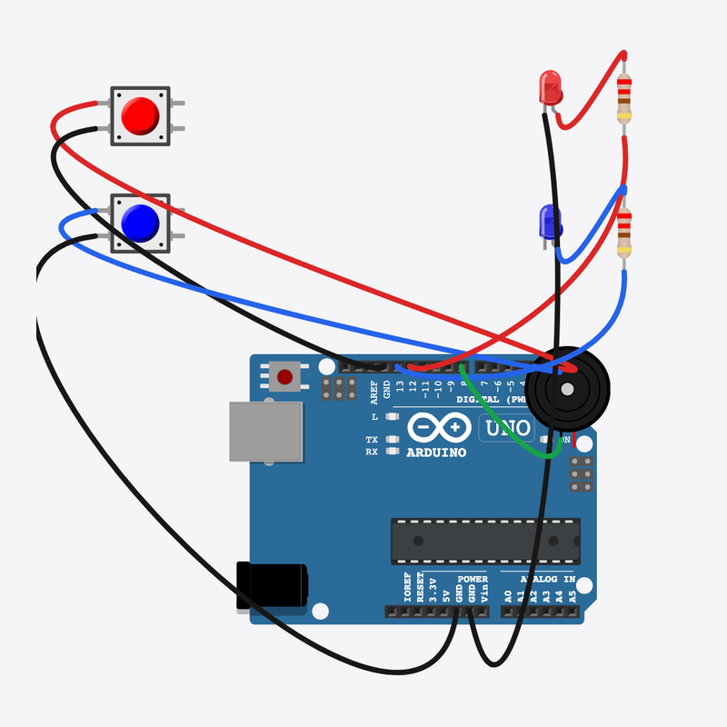
Pin connections
| Part 1 | Part 2 | |
|---|---|---|
Arduino pin 2 | → | Player A button pin 1 |
Player A button pin 2 | → | Arduino GND |
Arduino pin 3 | → | Player B button pin 1 |
Player B button pin 2 | → | Arduino GND |
Arduino pin 12 | → | Resistor A pin 2 |
Resistor A pin 1 | → | Player A LED anode (+) |
Player A LED cathode (-) | → | Arduino GND |
Arduino pin 13 | → | Resistor B pin 2 |
Resistor B pin 1 | → | Player B LED anode (+) |
Player B LED cathode (-) | → | Arduino GND |
Arduino pin 8 | → | Buzzer pin 1 (+) |
Buzzer pin 2 (-) | → | Arduino GND |
First press wins!
Two players, one buzzer — locked stops the other from scoring.
Quiz shows use exactly this “first valid input wins” logic.
The problem
Two inputs can fire at once — you need rules for who wins.
Think of it like
Like slapping a buzzer in trivia — first hand down locks the round.
Runs your sketch
Arduino
Brain
First press wins
Player A button
Input
Second player buzzes in
Player B button
Input
Shows A won the round
Player A LED
Output
Shows B won the round
Player B LED
Output
Protects A LED
Resistor A
Safety
Protects B LED
Resistor B
Safety
Celebrates the winner
Buzzer
Sound
Still open?
Only accept input while locked is false.
if (!locked && digitalRead(BTN_A) == LOW)
Player A wins
First valid press sets locked so B cannot win this round.
locked = true;
digitalWrite(LED_A, HIGH);
tone(BUZZER, 523);
Reset round
After both buttons release, locked clears for the next question.
resetRound();
Then loop back to step 1
Follow these steps in order. Match the wires to the colors shown.
Place Arduino
Place the Arduino (uno) on the breadboard.
Arduino placed!
Place Player A button
Place the Player A button (btnA) on the breadboard.
Place Player B button
Place the Player B button (btnB) on the breadboard.
Place Player A LED
Place the Player A LED (ledA) on the breadboard.
Place Player B LED
Place the Player B LED (ledB) on the breadboard.
Place Resistor A
Place the Resistor A (rA) on the breadboard.
Place Resistor B
Place the Resistor B (rB) on the breadboard.
Place Buzzer
Place the Buzzer (bz1) on the breadboard.
Connect Arduino pin 2 to Player A button (btnA) 1.l
Connect Arduino pin 2 to Player A button (btnA) 1.l.
Connect Player A button (btnA) 2.l to Arduino GND
Connect Player A button (btnA) 2.l to Arduino GND.
Connect Arduino pin 3 to Player B button (btnB) 1.l
Connect Arduino pin 3 to Player B button (btnB) 1.l.
Connect Player B button (btnB) 2.l to Arduino GND
Connect Player B button (btnB) 2.l to Arduino GND.
Connect Arduino pin 12 to Resistor A (rA) 2
Connect Arduino pin 12 to Resistor A (rA) 2.
Connect Resistor A (rA) 1 to Player A LED (ledA) anode (+)
Connect Resistor A (rA) 1 to Player A LED (ledA) anode (+).
Connect Player A LED (ledA) cathode (-) to Arduino GND
Connect Player A LED (ledA) cathode (-) to Arduino GND.
Connect Arduino pin 13 to Resistor B (rB) 2
Connect Arduino pin 13 to Resistor B (rB) 2.
Connect Resistor B (rB) 1 to Player B LED (ledB) anode (+)
Connect Resistor B (rB) 1 to Player B LED (ledB) anode (+).
Connect Player B LED (ledB) cathode (-) to Arduino GND
Connect Player B LED (ledB) cathode (-) to Arduino GND.
Connect Arduino pin 8 to Buzzer (bz1) 1
Connect Arduino pin 8 to Buzzer (bz1) 1.
Connect Buzzer (bz1) 2 to Arduino GND
Connect Buzzer (bz1) 2 to Arduino GND.
Lock flag
bool locked = false;
void resetRound() {
  locked = false;
  digitalWrite(LED_A, LOW);
  digitalWrite(LED_B, LOW);
  noTone(BUZZER);
}
locked is a boolean game rule — once true, other presses are ignored.
First-wins logic
void loop() {
  if (!locked && digitalRead(BTN_A) == LOW) {
    locked = true;
    digitalWrite(LED_A, HIGH);
    tone(BUZZER, 523, 500);
  } else if (!locked && digitalRead(BTN_B) == LOW) {
    locked = true;
    digitalWrite(LED_B, HIGH);
    tone(BUZZER, 440, 500);
  }
  if (locked && digitalRead(BTN_A) == HIGH && digitalRead(BTN_B) == HIGH) {
    delay(1500);
    resetRound();
  }
  delay(20);
}
if / else if checks A then B; resetRound() clears LEDs and locked.
const int BTN_A = 2;
const int BTN_B = 3;
const int LED_A = 12;
const int LED_B = 13;
const int BUZZER = 8;
bool locked = false;
void resetRound() {
  locked = false;
  digitalWrite(LED_A, LOW);
  digitalWrite(LED_B, LOW);
  noTone(BUZZER);
}
void setup() {
  pinMode(BTN_A, INPUT_PULLUP);
  pinMode(BTN_B, INPUT_PULLUP);
  pinMode(LED_A, OUTPUT);
  pinMode(LED_B, OUTPUT);
  pinMode(BUZZER, OUTPUT);
  resetRound();
}
void loop() {
  if (!locked && digitalRead(BTN_A) == LOW) {
    locked = true;
    digitalWrite(LED_A, HIGH);
    tone(BUZZER, 523, 500);
  } else if (!locked && digitalRead(BTN_B) == LOW) {
    locked = true;
    digitalWrite(LED_B, HIGH);
    tone(BUZZER, 440, 500);
  }
  if (locked && digitalRead(BTN_A) == HIGH && digitalRead(BTN_B) == HIGH) {
    delay(1500);
    resetRound();
  }
  delay(20);
}
Q1. Where does repeating work belong?
Q2. What does locked = true prevent?
Shorten between rounds — change delay(1500) to delay(800).
Hint: Line 32.
Comment line 23: // Player A wins first
Hint: Inside the first if block.
A line-by-line tour of the sketch — the same steps as in Robo Gurukul Studio.
Program overview
Technical
Sketches have globals, then setup() once, then loop() forever.
In this project
Two players race — first button press wins and locks out the other.
Why here
Read from top to bottom. Hover words or lines for help!
const int BTN_A = 2;
const int BTN_B = 3;
const int LED_A = 12;
const int LED_B = 13;
const int BUZZER = 8;
bool locked = false;
void resetRound() {
  locked = false;
  digitalWrite(LED_A, LOW);
  digitalWrite(LED_B, LOW);
  noTone(BUZZER);
}
setup()
Technical
Runs one time when the board turns on.
In this project
Sets up pins and libraries for Quiz Buzzer.
Why here
One-time setup belongs here—not in loop().
void setup() {
  pinMode(BTN_A, INPUT_PULLUP);
  pinMode(BTN_B, INPUT_PULLUP);
  pinMode(LED_A, OUTPUT);
  pinMode(LED_B, OUTPUT);
  pinMode(BUZZER, OUTPUT);
  resetRound();
}
loop()
Technical
Runs again and again after setup() is done.
In this project
This is the main action you see in Quiz Buzzer.
Why here
Repeating work (blink, read sensors) goes here.
void loop() {
  if (!locked && digitalRead(BTN_A) == LOW) {
    locked = true;
    digitalWrite(LED_A, HIGH);
    tone(BUZZER, 523, 500);
  } else if (!locked && digitalRead(BTN_B) == LOW) {
    locked = true;
    digitalWrite(LED_B, HIGH);
    tone(BUZZER, 440, 500);
  }
  if (locked && digitalRead(BTN_A) == HIGH && digitalRead(BTN_B) == HIGH) {
    delay(1500);
    resetRound();
  }
  delay(20);
}
Try this: Change numbers in loop(), then compile and run the simulator.
pinMode
Technical
Tells a pin if it listens or drives something.
In this project
Gets the Quiz Buzzer circuit ready in the simulator.
Why here
Goes in setup() because we only set pins once at the start.
pinMode(BTN_A, INPUT_PULLUP);
digitalWrite
Technical
Turns a pin ON or OFF.
In this project
Controls lights, motors, or buzzers in Quiz Buzzer.
Why here
Goes in loop() so it can keep changing while the program runs.
digitalWrite(LED_A, LOW);
digitalRead
Technical
Checks if a pin is ON or OFF.
In this project
Reads buttons or sensors in Quiz Buzzer.
Why here
Goes in loop() so we can react when something changes.
if (!locked && digitalRead(BTN_A) == LOW) {tone
Technical
Plays a beep on a buzzer pin at a chosen pitch.
In this project
Makes sounds in Quiz Buzzer.
Why here
Goes in loop() when you want notes or alarms.
tone(BUZZER, 523, 500);
noTone
Technical
Stops the buzzer sound on that pin.
In this project
Turns off the sound in Quiz Buzzer.
Why here
After tone() or before a pause so the buzzer is silent.
noTone(BUZZER);
delay
Technical
Waits for some time. Nothing else runs during the wait.
In this project
Controls speed so you can see Quiz Buzzer in the simulator.
Why here
Right after an action that should stay the same for a moment.
delay(1500);