Runs your sketch
Arduino
Brain
Loading part…
nested loops and pattern tables
Show different bar graph patterns stored in tables and loops.
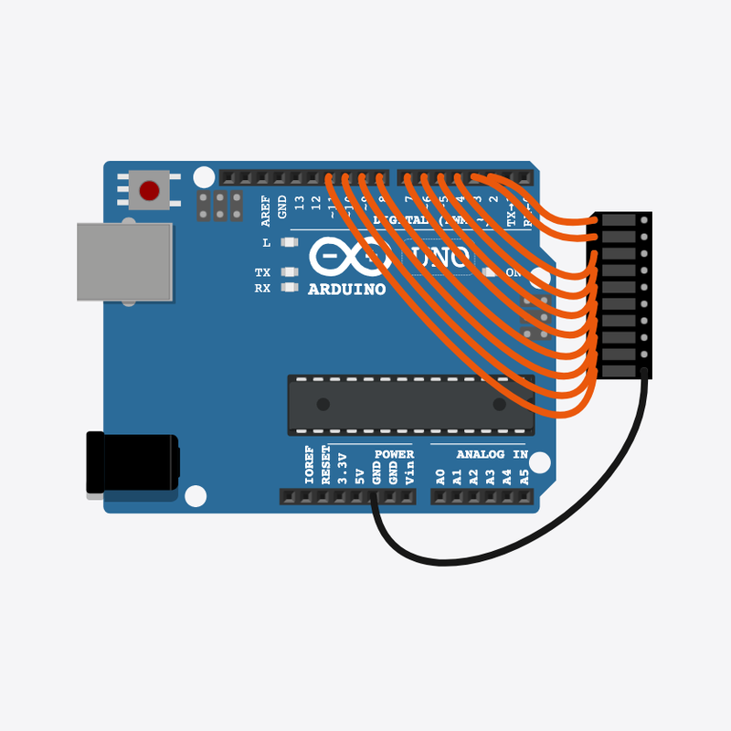
Pin connections
| Part 1 | Part 2 | |
|---|---|---|
Arduino pin 2 | → | LED bar graph A1 |
Arduino pin 3 | → | LED bar graph A2 |
Arduino pin 4 | → | LED bar graph A3 |
Arduino pin 5 | → | LED bar graph A4 |
Arduino pin 6 | → | LED bar graph A5 |
Arduino pin 7 | → | LED bar graph A6 |
Arduino pin 8 | → | LED bar graph A7 |
Arduino pin 9 | → | LED bar graph A8 |
Arduino pin 10 | → | LED bar graph A9 |
Arduino pin 11 | → | LED bar graph A10 |
LED bar graph C10 | → | Arduino GND |
Patterns stored in tables!
Arrays and loops replay different ON/OFF shapes on the bar.
Displays often look up patterns from tables instead of typing each step.
The problem
Writing every LED by hand gets tedious — reuse pattern data.
Think of it like
Like reading sheet music: the notes are written once, played in a loop.
Runs your sketch
Arduino
Brain
Ten segments you can light up
LED bar graph
Display
Show stripes
patternA[] is a table of 1s and 0s — the loop in showPattern() writes each segment ON or OFF.
showPattern(patternA);
delay(400);
Show pairs
patternB[] is a different shape on the bar — same function, different data.
showPattern(patternB);
delay(400);
Show center block
Then loop() starts again with patternA. Tables + loops avoid rewriting every LED by hand.
showPattern(patternC);
delay(400);
Then loop back to step 1
Follow these steps in order. Match the wires to the colors shown.
Place Arduino
Place the Arduino (uno) on the breadboard.
Arduino placed!
Place LED bar graph
Place the LED bar graph (bar1) on the breadboard.
Connect Arduino pin 2 to LED bar graph (bar1) A1
Connect Arduino pin 2 to LED bar graph (bar1) A1.
Connect Arduino pin 3 to LED bar graph (bar1) A2
Connect Arduino pin 3 to LED bar graph (bar1) A2.
Connect Arduino pin 4 to LED bar graph (bar1) A3
Connect Arduino pin 4 to LED bar graph (bar1) A3.
Connect Arduino pin 5 to LED bar graph (bar1) A4
Connect Arduino pin 5 to LED bar graph (bar1) A4.
Connect Arduino pin 6 to LED bar graph (bar1) A5
Connect Arduino pin 6 to LED bar graph (bar1) A5.
Connect Arduino pin 7 to LED bar graph (bar1) A6
Connect Arduino pin 7 to LED bar graph (bar1) A6.
Connect Arduino pin 8 to LED bar graph (bar1) A7
Connect Arduino pin 8 to LED bar graph (bar1) A7.
Connect Arduino pin 9 to LED bar graph (bar1) A8
Connect Arduino pin 9 to LED bar graph (bar1) A8.
Connect Arduino pin 10 to LED bar graph (bar1) A9
Connect Arduino pin 10 to LED bar graph (bar1) A9.
Connect Arduino pin 11 to LED bar graph (bar1) A10
Connect Arduino pin 11 to LED bar graph (bar1) A10.
Connect LED bar graph (bar1) C10 to Arduino GND
Connect LED bar graph (bar1) C10 to Arduino GND.
Pattern tables
const byte patternA[] = {1, 0, 1, 0, 1, 0, 1, 0, 1, 0};
const byte patternB[] = {1, 1, 0, 0, 1, 1, 0, 0, 1, 1};
const byte patternC[] = {0, 0, 0, 0, 1, 1, 1, 1, 0, 0};
Each array stores which segments are on (1) or off (0). Adding a new look means a new table, not ten new lines.
showPattern()
void showPattern(const byte *pat) {
  for (int i = 0; i < NUM_LEDS; i++) {
    digitalWrite(FIRST_PIN + i, pat[i] ? HIGH : LOW);
  }
}
One for-loop walks the table and calls digitalWrite for each segment. Reuse this function for every pattern.
Play patterns in loop
void loop() {
  showPattern(patternA);
  delay(400);
  showPattern(patternB);
  delay(400);
  showPattern(patternC);
  delay(400);
}
loop() calls showPattern three times with pauses — that is the full repeating show.
const int FIRST_PIN = 2;
const int NUM_LEDS = 10;
const byte patternA[] = {1, 0, 1, 0, 1, 0, 1, 0, 1, 0};
const byte patternB[] = {1, 1, 0, 0, 1, 1, 0, 0, 1, 1};
const byte patternC[] = {0, 0, 0, 0, 1, 1, 1, 1, 0, 0};
void showPattern(const byte *pat) {
  for (int i = 0; i < NUM_LEDS; i++) {
    digitalWrite(FIRST_PIN + i, pat[i] ? HIGH : LOW);
  }
}
void setup() {
  for (int i = 0; i < NUM_LEDS; i++) {
    pinMode(FIRST_PIN + i, OUTPUT);
  }
}
void loop() {
  showPattern(patternA);
  delay(400);
  showPattern(patternB);
  delay(400);
  showPattern(patternC);
  delay(400);
}
Q1. Where does repeating work belong?
Q2. Why store patterns in arrays like patternA[]?
Speed up the show — change all delay(400) to delay(200).
Hint: There are three delay(400) lines in loop().
Flip one segment in patternA — change a 1 to 0 or a 0 to 1 on line 3.
Hint: Edit the numbers inside the curly braces of patternA.
A line-by-line tour of the sketch — the same steps as in Robo Gurukul Studio.
Program overview
Technical
Sketches have globals, then setup() once, then loop() forever.
In this project
Show different bar graph patterns stored in tables and loops.
Why here
Read from top to bottom. Hover words or lines for help!
const int FIRST_PIN = 2;
const int NUM_LEDS = 10;
const byte patternA[] = {1, 0, 1, 0, 1, 0, 1, 0, 1, 0};
const byte patternB[] = {1, 1, 0, 0, 1, 1, 0, 0, 1, 1};
const byte patternC[] = {0, 0, 0, 0, 1, 1, 1, 1, 0, 0};
void showPattern(const byte *pat) {
  for (int i = 0; i < NUM_LEDS; i++) {
    digitalWrite(FIRST_PIN + i, pat[i] ? HIGH : LOW);
  }
}
setup()
Technical
Runs one time when the board turns on.
In this project
Sets up pins and libraries for Multiple LED Patterns.
Why here
One-time setup belongs here—not in loop().
void setup() {
  for (int i = 0; i < NUM_LEDS; i++) {
    pinMode(FIRST_PIN + i, OUTPUT);
  }
}
loop()
Technical
Runs again and again after setup() is done.
In this project
This is the main action you see in Multiple LED Patterns.
Why here
Repeating work (blink, read sensors) goes here.
void loop() {
  showPattern(patternA);
  delay(400);
  showPattern(patternB);
  delay(400);
  showPattern(patternC);
  delay(400);
}
Try this: Change numbers in loop(), then compile and run the simulator.
pinMode
Technical
Tells a pin if it listens or drives something.
In this project
Gets the Multiple LED Patterns circuit ready in the simulator.
Why here
Goes in setup() because we only set pins once at the start.
pinMode(FIRST_PIN + i, OUTPUT);
digitalWrite
Technical
Turns a pin ON or OFF.
In this project
Controls lights, motors, or buzzers in Multiple LED Patterns.
Why here
Goes in loop() so it can keep changing while the program runs.
digitalWrite(FIRST_PIN + i, pat[i] ? HIGH : LOW);
delay
Technical
Waits for some time. Nothing else runs during the wait.
In this project
Controls speed so you can see Multiple LED Patterns in the simulator.
Why here
Right after an action that should stay the same for a moment.
delay(400);