Runs your sketch
Arduino
Brain
Loading part…
changing delay() values
Alternate fast and slow blink speeds by changing delay() values.
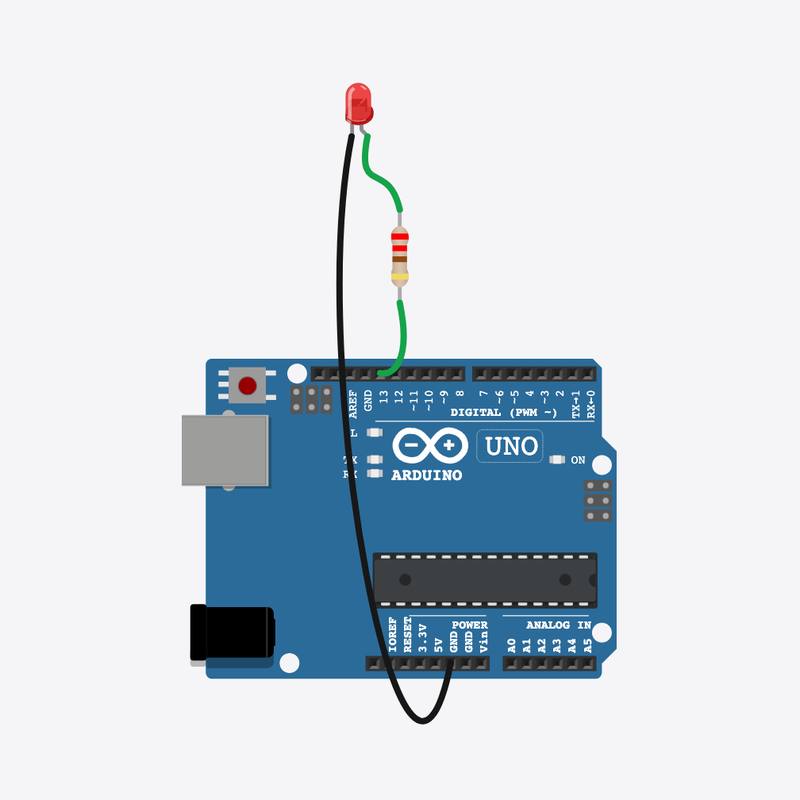
Pin connections
| Part 1 | Part 2 | |
|---|---|---|
Arduino pin 13 | → | Resistor pin 2 |
Resistor pin 1 | → | LED anode (+) |
LED cathode (-) | → | Arduino GND |
Same blink — two speeds!
Change delay() numbers to make the LED blink fast, then slow.
Different blink speeds mean different things on real devices.
The problem
One blink speed is boring — you want to control timing.
Think of it like
Like clapping fast then slow — the action is the same, the pause changes.
Runs your sketch
Arduino
Brain
Limits current to the LED
Resistor
Safety
Shows output from the code
LED
Light
Blink fast — ON
The LED turns on, then waits only 150 ms — a quick flash.
digitalWrite(LED_PIN, HIGH);
delay(FAST_MS);
Blink fast — OFF
Same short pause with the LED off. FAST_MS controls both quick blinks.
digitalWrite(LED_PIN, LOW);
delay(FAST_MS);
Blink slow — ON
Now delay(SLOW_MS) keeps the LED on much longer — easy to see the difference.
digitalWrite(LED_PIN, HIGH);
delay(SLOW_MS);
Blink slow — OFF
After the long pause, loop() starts over with fast blinks again.
digitalWrite(LED_PIN, LOW);
delay(SLOW_MS);
Then loop back to step 1
Follow these steps in order. Match the wires to the colors shown.
Place Arduino
Place the Arduino (uno) on the breadboard.
Arduino placed!
Place Resistor
Place the Resistor (r1) on the breadboard.
Place LED
Place the LED (led1) on the breadboard.
Connect Arduino pin 13 to Resistor (r1) 2
Connect Arduino pin 13 to Resistor (r1) 2.
Connect Resistor (r1) 1 to LED (led1) anode (+)
Connect Resistor (r1) 1 to LED (led1) anode (+).
Connect LED (led1) cathode (-) to Arduino GND
Connect LED (led1) cathode (-) to Arduino GND.
Timing constants
const int LED_PIN = 13;
const int FAST_MS = 150;
const int SLOW_MS = 800;
FAST_MS and SLOW_MS are names for two different delay() lengths. Change these numbers to retune the whole pattern.
Setup the pin
void setup() {
  pinMode(LED_PIN, OUTPUT);
}
setup() runs once and sets pin 13 as an output so we can drive the LED.
Fast then slow loop
void loop() {
  digitalWrite(LED_PIN, HIGH);
  delay(FAST_MS);
  digitalWrite(LED_PIN, LOW);
  delay(FAST_MS);
  digitalWrite(LED_PIN, HIGH);
  delay(SLOW_MS);
  digitalWrite(LED_PIN, LOW);
  delay(SLOW_MS);
}
loop() alternates two fast blinks, then two slow blinks. The delay() numbers — not digitalWrite — set the speed.
const int LED_PIN = 13;
const int FAST_MS = 150;
const int SLOW_MS = 800;
void setup() {
  pinMode(LED_PIN, OUTPUT);
}
void loop() {
  digitalWrite(LED_PIN, HIGH);
  delay(FAST_MS);
  digitalWrite(LED_PIN, LOW);
  delay(FAST_MS);
  digitalWrite(LED_PIN, HIGH);
  delay(SLOW_MS);
  digitalWrite(LED_PIN, LOW);
  delay(SLOW_MS);
}
Q1. Where does repeating work belong?
Q2. What does a bigger number inside delay() do?
Make the fast blinks even quicker by lowering FAST_MS (try 80 or 100).
Hint: Edit the number on the line with FAST_MS = 150.
Make the slow blinks longer by raising SLOW_MS (try 1200 or 1500).
Hint: Edit the line with SLOW_MS = 800.
A line-by-line tour of the sketch — the same steps as in Robo Gurukul Studio.
Program overview
Technical
Sketches have globals, then setup() once, then loop() forever.
In this project
Alternate fast and slow blink speeds by changing delay() values.
Why here
Read from top to bottom. Hover words or lines for help!
const int LED_PIN = 13;
const int FAST_MS = 150;
const int SLOW_MS = 800;
setup()
Technical
Runs one time when the board turns on.
In this project
Sets up pins and libraries for Fast & Slow Blink.
Why here
One-time setup belongs here—not in loop().
void setup() {
  pinMode(LED_PIN, OUTPUT);
}
loop()
Technical
Runs again and again after setup() is done.
In this project
This is the main action you see in Fast & Slow Blink.
Why here
Repeating work (blink, read sensors) goes here.
void loop() {
  digitalWrite(LED_PIN, HIGH);
  delay(FAST_MS);
  digitalWrite(LED_PIN, LOW);
  delay(FAST_MS);
  digitalWrite(LED_PIN, HIGH);
  delay(SLOW_MS);
  digitalWrite(LED_PIN, LOW);
  delay(SLOW_MS);
}
Try this: Change numbers in loop(), then compile and run the simulator.
pinMode
Technical
Tells a pin if it listens or drives something.
In this project
Gets the Fast & Slow Blink circuit ready in the simulator.
Why here
Goes in setup() because we only set pins once at the start.
pinMode(LED_PIN, OUTPUT);
digitalWrite
Technical
Turns a pin ON or OFF.
In this project
Controls lights, motors, or buzzers in Fast & Slow Blink.
Why here
Goes in loop() so it can keep changing while the program runs.
digitalWrite(LED_PIN, HIGH);
delay
Technical
Waits for some time. Nothing else runs during the wait.
In this project
Controls speed so you can see Fast & Slow Blink in the simulator.
Why here
Right after an action that should stay the same for a moment.
delay(FAST_MS);