Runs your sketch
Arduino
Brain
Loading part…
timed show sequences
Run a timed light show sequence on a bar graph.
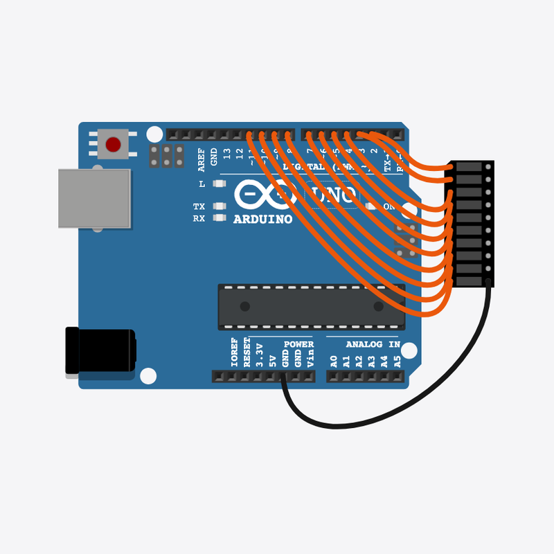
Pin connections
| Part 1 | Part 2 | |
|---|---|---|
Arduino pin 2 | → | LED bar graph A1 |
Arduino pin 3 | → | LED bar graph A2 |
Arduino pin 4 | → | LED bar graph A3 |
Arduino pin 5 | → | LED bar graph A4 |
Arduino pin 6 | → | LED bar graph A5 |
Arduino pin 7 | → | LED bar graph A6 |
Arduino pin 8 | → | LED bar graph A7 |
Arduino pin 9 | → | LED bar graph A8 |
Arduino pin 10 | → | LED bar graph A9 |
Arduino pin 11 | → | LED bar graph A10 |
LED bar graph C10 | → | Arduino GND |
Your own light show sequence!
Wave in, wave out, then blink all — a timed multi-step show.
Stage lights and signs run scripted sequences like this.
The problem
One pattern is not enough — chain several timed acts together.
Think of it like
Like a dance routine: step one, step two, finale.
Runs your sketch
Arduino
Brain
Ten segments you can light up
LED bar graph
Display
Act 1 — wave in
One segment at a time turns on from left to right — the bar fills up.
digitalWrite(FIRST_PIN + i, HIGH);
delay(80);
Hold full bar
Every segment stays on briefly before the next act.
delay(500);
Act 2 — wave out
Segments turn off one by one from right to left.
digitalWrite(FIRST_PIN + i, LOW);
delay(80);
Act 3 — blink together
The whole bar flashes three times — a finale before the pause.
allOn(); delay(150); allOff(); delay(150);
Reset and repeat
A long pause, then loop() runs the whole show from Act 1 again.
delay(800);
Then loop back to step 1
Follow these steps in order. Match the wires to the colors shown.
Place Arduino
Place the Arduino (uno) on the breadboard.
Arduino placed!
Place LED bar graph
Place the LED bar graph (bar1) on the breadboard.
Connect Arduino pin 2 to LED bar graph (bar1) A1
Connect Arduino pin 2 to LED bar graph (bar1) A1.
Connect Arduino pin 3 to LED bar graph (bar1) A2
Connect Arduino pin 3 to LED bar graph (bar1) A2.
Connect Arduino pin 4 to LED bar graph (bar1) A3
Connect Arduino pin 4 to LED bar graph (bar1) A3.
Connect Arduino pin 5 to LED bar graph (bar1) A4
Connect Arduino pin 5 to LED bar graph (bar1) A4.
Connect Arduino pin 6 to LED bar graph (bar1) A5
Connect Arduino pin 6 to LED bar graph (bar1) A5.
Connect Arduino pin 7 to LED bar graph (bar1) A6
Connect Arduino pin 7 to LED bar graph (bar1) A6.
Connect Arduino pin 8 to LED bar graph (bar1) A7
Connect Arduino pin 8 to LED bar graph (bar1) A7.
Connect Arduino pin 9 to LED bar graph (bar1) A8
Connect Arduino pin 9 to LED bar graph (bar1) A8.
Connect Arduino pin 10 to LED bar graph (bar1) A9
Connect Arduino pin 10 to LED bar graph (bar1) A9.
Connect Arduino pin 11 to LED bar graph (bar1) A10
Connect Arduino pin 11 to LED bar graph (bar1) A10.
Connect LED bar graph (bar1) C10 to Arduino GND
Connect LED bar graph (bar1) C10 to Arduino GND.
Helper functions
void allOff() {
  for (int i = 0; i < NUM_LEDS; i++) {
    digitalWrite(FIRST_PIN + i, LOW);
  }
}
void allOn() {
  for (int i = 0; i < NUM_LEDS; i++) {
    digitalWrite(FIRST_PIN + i, HIGH);
  }
}
allOff() and allOn() use loops so we do not write ten digitalWrite lines by hand.
Setup the bar
void setup() {
  for (int i = 0; i < NUM_LEDS; i++) {
    pinMode(FIRST_PIN + i, OUTPUT);
  }
}
Every bar pin is set to OUTPUT once in setup().
Full show sequence
void loop() {
  for (int i = 0; i < NUM_LEDS; i++) {
    digitalWrite(FIRST_PIN + i, HIGH);
    delay(80);
  }
  delay(500);
  for (int i = NUM_LEDS - 1; i >= 0; i--) {
    digitalWrite(FIRST_PIN + i, LOW);
    delay(80);
  }
  delay(300);
  for (int n = 0; n < 3; n++) {
    allOn();
    delay(150);
    allOff();
    delay(150);
  }
  delay(800);
}
loop() chains wave-in, pause, wave-out, blink finale, and rest — a timed light show.
const int FIRST_PIN = 2;
const int NUM_LEDS = 10;
void allOff() {
  for (int i = 0; i < NUM_LEDS; i++) {
    digitalWrite(FIRST_PIN + i, LOW);
  }
}
void allOn() {
  for (int i = 0; i < NUM_LEDS; i++) {
    digitalWrite(FIRST_PIN + i, HIGH);
  }
}
void setup() {
  for (int i = 0; i < NUM_LEDS; i++) {
    pinMode(FIRST_PIN + i, OUTPUT);
  }
}
void loop() {
  for (int i = 0; i < NUM_LEDS; i++) {
    digitalWrite(FIRST_PIN + i, HIGH);
    delay(80);
  }
  delay(500);
  for (int i = NUM_LEDS - 1; i >= 0; i--) {
    digitalWrite(FIRST_PIN + i, LOW);
    delay(80);
  }
  delay(300);
  for (int n = 0; n < 3; n++) {
    allOn();
    delay(150);
    allOff();
    delay(150);
  }
  delay(800);
}
Q1. Where does repeating work belong?
Q2. What makes this a "show sequence"?
Speed up the wave — change delay(80) to delay(40) in both wave loops.
Hint: Lines inside the for-loops that light segments one by one.
Add one extra flash — change the blink loop from n < 3 to n < 4.
Hint: Find for (int n = 0; n < 3; n++).
A line-by-line tour of the sketch — the same steps as in Robo Gurukul Studio.
Program overview
Technical
Sketches have globals, then setup() once, then loop() forever.
In this project
Run a timed light show sequence on a bar graph.
Why here
Read from top to bottom. Hover words or lines for help!
const int FIRST_PIN = 2;
const int NUM_LEDS = 10;
void allOff() {
  for (int i = 0; i < NUM_LEDS; i++) {
    digitalWrite(FIRST_PIN + i, LOW);
  }
}
void allOn() {
  for (int i = 0; i < NUM_LEDS; i++) {
    digitalWrite(FIRST_PIN + i, HIGH);
  }
}
setup()
Technical
Runs one time when the board turns on.
In this project
Sets up pins and libraries for Mini Light Show.
Why here
One-time setup belongs here—not in loop().
void setup() {
  for (int i = 0; i < NUM_LEDS; i++) {
    pinMode(FIRST_PIN + i, OUTPUT);
  }
}
loop()
Technical
Runs again and again after setup() is done.
In this project
This is the main action you see in Mini Light Show.
Why here
Repeating work (blink, read sensors) goes here.
void loop() {
  for (int i = 0; i < NUM_LEDS; i++) {
    digitalWrite(FIRST_PIN + i, HIGH);
    delay(80);
  }
  delay(500);
  for (int i = NUM_LEDS - 1; i >= 0; i--) {
    digitalWrite(FIRST_PIN + i, LOW);
    delay(80);
  }
  delay(300);
  for (int n = 0; n < 3; n++) {
    allOn();
    delay(150);
    allOff();
    delay(150);
  }
  delay(800);
}
Try this: Change numbers in loop(), then compile and run the simulator.
pinMode
Technical
Tells a pin if it listens or drives something.
In this project
Gets the Mini Light Show circuit ready in the simulator.
Why here
Goes in setup() because we only set pins once at the start.
pinMode(FIRST_PIN + i, OUTPUT);
digitalWrite
Technical
Turns a pin ON or OFF.
In this project
Controls lights, motors, or buzzers in Mini Light Show.
Why here
Goes in loop() so it can keep changing while the program runs.
digitalWrite(FIRST_PIN + i, LOW);
delay
Technical
Waits for some time. Nothing else runs during the wait.
In this project
Controls speed so you can see Mini Light Show in the simulator.
Why here
Right after an action that should stay the same for a moment.
delay(80);