Runs your sketch
Arduino
Brain
Loading part…
alternating output states
Turn two LEDs on and off in opposite states.
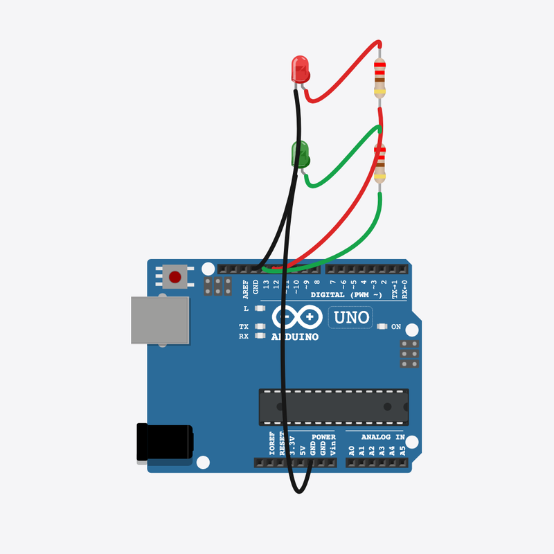
Pin connections
| Part 1 | Part 2 | |
|---|---|---|
Arduino pin 12 | → | Red resistor pin 2 |
Red resistor pin 1 | → | Red LED anode (+) |
Red LED cathode (-) | → | Arduino GND |
Arduino pin 13 | → | Green resistor pin 2 |
Green resistor pin 1 | → | Green LED anode (+) |
Green LED cathode (-) | → | Arduino GND |
When one is ON, the other is OFF!
Two LEDs take opposite states — like a seesaw.
Direction indicators and turn signals alternate outputs.
The problem
You need two outputs that never match at the same time.
Think of it like
Like a seesaw — one side up means the other is down.
Runs your sketch
Arduino
Brain
First alternating light
Red LED
Output A
Second alternating light
Green LED
Output B
Protects the red LED
Red resistor
Safety
Protects the green LED
Green resistor
Safety
LED A wins
Pin 12 is HIGH while pin 13 is LOW — opposite states on purpose.
digitalWrite(LED_A, HIGH);
digitalWrite(LED_B, LOW);
Hold
Both states stay visible for 300 ms so you can see who is on.
delay(300);
LED B wins
Now the roles flip — A off, B on. Like a seesaw.
digitalWrite(LED_A, LOW);
digitalWrite(LED_B, HIGH);
Hold and repeat
Another pause, then loop() swaps back to A again.
delay(300);
Then loop back to step 1
Follow these steps in order. Match the wires to the colors shown.
Place Arduino
Place the Arduino (uno) on the breadboard.
Arduino placed!
Place Red LED
Place the Red LED (ledA) on the breadboard.
Place Green LED
Place the Green LED (ledB) on the breadboard.
Place Red resistor
Place the Red resistor (rA) on the breadboard.
Place Green resistor
Place the Green resistor (rB) on the breadboard.
Connect Arduino pin 12 to Red resistor (rA) 2
Connect Arduino pin 12 to Red resistor (rA) 2.
Connect Red resistor (rA) 1 to Red LED (ledA) anode (+)
Connect Red resistor (rA) 1 to Red LED (ledA) anode (+).
Connect Red LED (ledA) cathode (-) to Arduino GND
Connect Red LED (ledA) cathode (-) to Arduino GND.
Connect Arduino pin 13 to Green resistor (rB) 2
Connect Arduino pin 13 to Green resistor (rB) 2.
Connect Green resistor (rB) 1 to Green LED (ledB) anode (+)
Connect Green resistor (rB) 1 to Green LED (ledB) anode (+).
Connect Green LED (ledB) cathode (-) to Arduino GND
Connect Green LED (ledB) cathode (-) to Arduino GND.
Two output pins
const int LED_A = 12;
const int LED_B = 13;
LED_A and LED_B name the two pins we alternate between.
Setup both pins
void setup() {
  pinMode(LED_A, OUTPUT);
  pinMode(LED_B, OUTPUT);
}
Both pins are outputs so we can drive two LEDs independently.
Alternate loop
void loop() {
  digitalWrite(LED_A, HIGH);
  digitalWrite(LED_B, LOW);
  delay(300);
  digitalWrite(LED_A, LOW);
  digitalWrite(LED_B, HIGH);
  delay(300);
}
Each half of loop() sets opposite HIGH/LOW pairs, with delay() between swaps.
const int LED_A = 12;
const int LED_B = 13;
void setup() {
  pinMode(LED_A, OUTPUT);
  pinMode(LED_B, OUTPUT);
}
void loop() {
  digitalWrite(LED_A, HIGH);
  digitalWrite(LED_B, LOW);
  delay(300);
  digitalWrite(LED_A, LOW);
  digitalWrite(LED_B, HIGH);
  delay(300);
}
Q1. Where does repeating work belong?
Q2. When LED A is HIGH, LED B should be…
Swap faster — change both delay(300) to delay(150).
Hint: There are two matching delay lines in loop().
Add a comment on the first digitalWrite(LED_A, HIGH) line explaining “A on”.
Hint: Use // at the end of line 8.
A line-by-line tour of the sketch — the same steps as in Robo Gurukul Studio.
Program overview
Technical
Sketches have globals, then setup() once, then loop() forever.
In this project
Turn two LEDs on and off in opposite states.
Why here
Read from top to bottom. Hover words or lines for help!
const int LED_A = 12;
const int LED_B = 13;
setup()
Technical
Runs one time when the board turns on.
In this project
Sets up pins and libraries for Alternate LEDs.
Why here
One-time setup belongs here—not in loop().
void setup() {
  pinMode(LED_A, OUTPUT);
  pinMode(LED_B, OUTPUT);
}
loop()
Technical
Runs again and again after setup() is done.
In this project
This is the main action you see in Alternate LEDs.
Why here
Repeating work (blink, read sensors) goes here.
void loop() {
  digitalWrite(LED_A, HIGH);
  digitalWrite(LED_B, LOW);
  delay(300);
  digitalWrite(LED_A, LOW);
  digitalWrite(LED_B, HIGH);
  delay(300);
}
Try this: Change numbers in loop(), then compile and run the simulator.
pinMode
Technical
Tells a pin if it listens or drives something.
In this project
Gets the Alternate LEDs circuit ready in the simulator.
Why here
Goes in setup() because we only set pins once at the start.
pinMode(LED_A, OUTPUT);
digitalWrite
Technical
Turns a pin ON or OFF.
In this project
Controls lights, motors, or buzzers in Alternate LEDs.
Why here
Goes in loop() so it can keep changing while the program runs.
digitalWrite(LED_A, HIGH);
delay
Technical
Waits for some time. Nothing else runs during the wait.
In this project
Controls speed so you can see Alternate LEDs in the simulator.
Why here
Right after an action that should stay the same for a moment.
delay(300);