Runs your sketch
Arduino
Brain
Loading part…
millis() with if conditions
Measure button reaction time with millis() after a random GO signal.
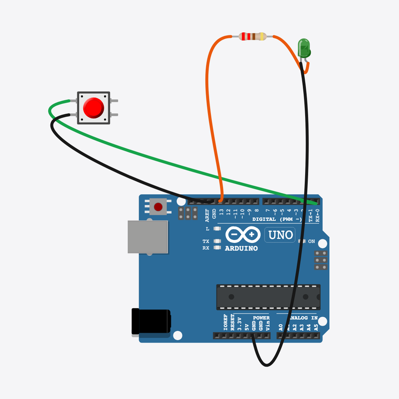
Pin connections
| Part 1 | Part 2 | |
|---|---|---|
Arduino pin 2 | → | Button pin 1 |
Button pin 2 | → | Arduino GND |
Arduino pin 13 | → | Resistor pin 1 |
Resistor pin 2 | → | GO LED anode (+) |
GO LED cathode (-) | → | Arduino GND |
Time reactions with millis()!
Wait… wait… GO! Press as fast as you can — millis() measures your speed.
Games and sports timers use millis() so other code can still run.
The problem
delay() would freeze everything — you need a clock that keeps ticking.
Think of it like
millis() is a stopwatch that never stops counting milliseconds.
Runs your sketch
Arduino
Brain
Press when GO lights up
Button
Input
Protects the GO LED
Resistor
Safety
Tells you when to press
GO LED
Signal
Wait random time
No delay() — we compare millis() to a target time stored in waitUntil.
if (state == WAIT && millis() >= waitUntil)
Show GO
LED turns on and we record the exact moment with goTime.
digitalWrite(GO_LED, HIGH);
goTime = millis();
Measure reaction
Subtract goTime from now to get milliseconds since GO.
reaction = millis() - goTime;
Then loop back to step 1
Follow these steps in order. Match the wires to the colors shown.
Place Arduino
Place the Arduino (uno) on the breadboard.
Arduino placed!
Place Button
Place the Button (btn1) on the breadboard.
Place Resistor
Place the Resistor (r1) on the breadboard.
Place GO LED
Place the GO LED (led1) on the breadboard.
Connect Arduino pin 2 to Button (btn1) 1.l
Connect Arduino pin 2 to Button (btn1) 1.l.
Connect Button (btn1) 2.l to Arduino GND
Connect Button (btn1) 2.l to Arduino GND.
Connect Arduino pin 13 to Resistor (r1) 1
Connect Arduino pin 13 to Resistor (r1) 1.
Connect Resistor (r1) 2 to GO LED (led1) anode (+)
Connect Resistor (r1) 2 to GO LED (led1) anode (+).
Connect GO LED (led1) cathode (-) to Arduino GND
Connect GO LED (led1) cathode (-) to Arduino GND.
State machine
enum State { WAIT, GO, SCORED };
State state = WAIT;
unsigned long goTime = 0;
unsigned long waitUntil = 0;
State enum tracks WAIT, GO, and SCORED — the program mode changes with if.
scheduleWait()
void scheduleWait() {
  digitalWrite(GO_LED, LOW);
  waitUntil = millis() + random(2000, 5000);
  state = WAIT;
}
Sets a future millis() target for the random wait — non-blocking timing.
Reaction math
void loop() {
  if (state == WAIT && millis() >= waitUntil) {
    digitalWrite(GO_LED, HIGH);
    goTime = millis();
    state = GO;
    Serial.println("GO! Press the button!");
  }
  if (state == GO && digitalRead(BUTTON_PIN) == LOW) {
    unsigned long reaction = millis() - goTime;
    Serial.print("Reaction: ");
    Serial.print(reaction);
    Serial.println(" ms");
    state = SCORED;
    delay(2000);
    scheduleWait();
  }
  delay(10);
loop() uses if on state and millis() to start GO and compute reaction time.
const int BUTTON_PIN = 2;
const int GO_LED = 13;
enum State { WAIT, GO, SCORED };
State state = WAIT;
unsigned long goTime = 0;
unsigned long waitUntil = 0;
void scheduleWait() {
  digitalWrite(GO_LED, LOW);
  waitUntil = millis() + random(2000, 5000);
  state = WAIT;
}
void setup() {
  pinMode(BUTTON_PIN, INPUT_PULLUP);
  pinMode(GO_LED, OUTPUT);
  Serial.begin(9600);
  randomSeed(analogRead(0));
  scheduleWait();
  Serial.println("Reaction Timer — wait for GO!");
}
void loop() {
  if (state == WAIT && millis() >= waitUntil) {
    digitalWrite(GO_LED, HIGH);
    goTime = millis();
    state = GO;
    Serial.println("GO! Press the button!");
  }
  if (state == GO && digitalRead(BUTTON_PIN) == LOW) {
    unsigned long reaction = millis() - goTime;
    Serial.print("Reaction: ");
    Serial.print(reaction);
    Serial.println(" ms");
    state = SCORED;
    delay(2000);
    scheduleWait();
  }
  delay(10);
}
Q1. Where does repeating work belong?
Q2. Why use millis() instead of delay() while waiting?
Make waits shorter — change random(2000, 5000) to random(1000, 3000) in scheduleWait().
Hint: Line 9.
Comment line 28 explaining reaction = time since GO.
Hint: The reaction = millis() - goTime line.
A line-by-line tour of the sketch — the same steps as in Robo Gurukul Studio.
Program overview
Technical
Sketches have globals, then setup() once, then loop() forever.
In this project
Measure button reaction time with millis() after a random GO signal.
Why here
Read from top to bottom. Hover words or lines for help!
const int BUTTON_PIN = 2;
const int GO_LED = 13;
enum State { WAIT, GO, SCORED };
State state = WAIT;
unsigned long goTime = 0;
unsigned long waitUntil = 0;
void scheduleWait() {
  digitalWrite(GO_LED, LOW);
  waitUntil = millis() + random(2000, 5000);
  state = WAIT;
}
setup()
Technical
Runs one time when the board turns on.
In this project
Sets up pins and libraries for Reaction Timer.
Why here
One-time setup belongs here—not in loop().
void setup() {
  pinMode(BUTTON_PIN, INPUT_PULLUP);
  pinMode(GO_LED, OUTPUT);
  Serial.begin(9600);
  randomSeed(analogRead(0));
  scheduleWait();
  Serial.println("Reaction Timer — wait for GO!");
}
loop()
Technical
Runs again and again after setup() is done.
In this project
This is the main action you see in Reaction Timer.
Why here
Repeating work (blink, read sensors) goes here.
void loop() {
  if (state == WAIT && millis() >= waitUntil) {
    digitalWrite(GO_LED, HIGH);
    goTime = millis();
    state = GO;
    Serial.println("GO! Press the button!");
  }
  if (state == GO && digitalRead(BUTTON_PIN) == LOW) {
    unsigned long reaction = millis() - goTime;
    Serial.print("Reaction: ");
    Serial.print(reaction);
    Serial.println(" ms");
    state = SCORED;
    delay(2000);
    scheduleWait();
  }
  delay(10);
}
Try this: Change numbers in loop(), then compile and run the simulator.
pinMode
Technical
Tells a pin if it listens or drives something.
In this project
Gets the Reaction Timer circuit ready in the simulator.
Why here
Goes in setup() because we only set pins once at the start.
pinMode(BUTTON_PIN, INPUT_PULLUP);
digitalWrite
Technical
Turns a pin ON or OFF.
In this project
Controls lights, motors, or buzzers in Reaction Timer.
Why here
Goes in loop() so it can keep changing while the program runs.
digitalWrite(GO_LED, LOW);
digitalRead
Technical
Checks if a pin is ON or OFF.
In this project
Reads buttons or sensors in Reaction Timer.
Why here
Goes in loop() so we can react when something changes.
if (state == GO && digitalRead(BUTTON_PIN) == LOW) {analogRead
Technical
Reads a sensor number from 0 to 1023.
In this project
Turns a sensor signal into a number for Reaction Timer.
Why here
Goes in loop() to keep checking the sensor.
randomSeed(analogRead(0));
delay
Technical
Waits for some time. Nothing else runs during the wait.
In this project
Controls speed so you can see Reaction Timer in the simulator.
Why here
Right after an action that should stay the same for a moment.
delay(2000);
millis
Technical
Counts milliseconds since the board started.
In this project
Tracks time in Reaction Timer without using delay().
Why here
In loop() when you need to know how much time passed.
waitUntil = millis() + random(2000, 5000);
random
Technical
Picks a random number in a range.
In this project
Adds randomness in Reaction Timer.
Why here
In loop() when you want different values each time.
waitUntil = millis() + random(2000, 5000);
begin
Technical
Starts talking to the computer screen (serial monitor).
In this project
Lets Reaction Timer print debug messages.
Why here
Goes in setup() once before any Serial.print.
Serial.begin(9600);
Technical
Sends text to the serial monitor without a new line.
In this project
Shows values from Reaction Timer on the screen.
Why here
In loop() or setup() when you want to see what the board is doing.
Serial.print("Reaction: ");println
Technical
Sends text to the serial monitor and starts a new line.
In this project
Prints one line of output for Reaction Timer.
Why here
In loop() when each reading should appear on its own line.
Serial.println("Reaction Timer — wait for GO!");