Runs your sketch
Arduino
Brain
Loading part…
armed and disarmed if tree
Arm or disarm an alarm with a button; motion triggers the buzzer when armed.
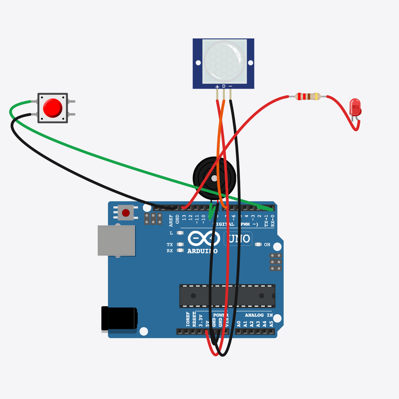
Pin connections
| Part 1 | Part 2 | |
|---|---|---|
Arduino pin 2 | → | Arm button pin 1 |
Arm button pin 2 | → | Arduino GND |
Motion sensor VCC | → | Arduino 5V |
Motion sensor GND | → | Arduino GND |
Motion sensor OUT | → | Arduino pin 7 |
Arduino pin 8 | → | Buzzer pin 1 (+) |
Buzzer pin 2 (-) | → | Arduino GND |
Arduino pin 13 | → | Resistor pin 1 |
Resistor pin 2 | → | Status LED anode (+) |
Status LED cathode (-) | → | Arduino GND |
Arm it — motion sounds the alarm!
Toggle armed with a button; if armed AND motion, buzzer rings.
Home alarms combine mode switches with sensor if conditions.
The problem
Real systems nest if tests — armed mode changes what motion means.
Think of it like
Like turning on a house alarm before leaving — only then does motion matter.
Runs your sketch
Arduino
Brain
Toggles armed/disarmed
Arm button
Input
Detects movement
Motion sensor
Input
Sounds when armed and motion
Buzzer
Alarm
Protects status LED
Resistor
Safety
On when system is armed
Status LED
Output
Toggle armed
Button edge flips armed and the status LED shows the mode.
armed = !armed;
Check motion
Both must be true — armed AND motion — before alarming.
if (armed && digitalRead(PIR_PIN) == HIGH)
Sound or silence
Buzzer on only in armed+motion; disarmed always silent.
tone(BUZZER, 880) / noTone(BUZZER)
Then loop back to step 1
Follow these steps in order. Match the wires to the colors shown.
Place Arduino
Place the Arduino (uno) on the breadboard.
Arduino placed!
Place Arm button
Place the Arm button (btn1) on the breadboard.
Place Motion sensor
Place the Motion sensor (pir1) on the breadboard.
Place Buzzer
Place the Buzzer (bz1) on the breadboard.
Place Resistor
Place the Resistor (r1) on the breadboard.
Place Status LED
Place the Status LED (led1) on the breadboard.
Connect Arduino pin 2 to Arm button (btn1) 1.l
Connect Arduino pin 2 to Arm button (btn1) 1.l.
Connect Arm button (btn1) 2.l to Arduino GND
Connect Arm button (btn1) 2.l to Arduino GND.
Connect Motion sensor (pir1) VCC to Arduino pin 5
Connect Motion sensor (pir1) VCC to Arduino pin 5.
Connect Motion sensor (pir1) GND to Arduino GND
Connect Motion sensor (pir1) GND to Arduino GND.
Connect Motion sensor (pir1) OUT to Arduino pin 7
Connect Motion sensor (pir1) OUT to Arduino pin 7.
Connect Arduino pin 8 to Buzzer (bz1) 1
Connect Arduino pin 8 to Buzzer (bz1) 1.
Connect Buzzer (bz1) 2 to Arduino GND
Connect Buzzer (bz1) 2 to Arduino GND.
Connect Arduino pin 13 to Resistor (r1) 1
Connect Arduino pin 13 to Resistor (r1) 1.
Connect Resistor (r1) 2 to Status LED (led1) anode (+)
Connect Resistor (r1) 2 to Status LED (led1) anode (+).
Connect Status LED (led1) cathode (-) to Arduino GND
Connect Status LED (led1) cathode (-) to Arduino GND.
Arm toggle
void loop() {
  bool btn = digitalRead(ARM_BTN);
  if (lastBtn == HIGH && btn == LOW) {
    armed = !armed;
    digitalWrite(STATUS_LED, armed ? HIGH : LOW);
    Serial.println(armed ? "ARMED" : "DISARMED");
    noTone(BUZZER);
  }
  lastBtn = btn;
Edge detection on the arm button flips armed and prints ARMED/DISARMED.
Nested if alarm
  if (armed && digitalRead(PIR_PIN) == HIGH) {
    tone(BUZZER, 880);
  } else {
    noTone(BUZZER);
  }
  delay(20);
armed && motion is an AND condition — classic security logic.
const int ARM_BTN = 2;
const int PIR_PIN = 7;
const int BUZZER = 8;
const int STATUS_LED = 13;
bool armed = false;
bool lastBtn = HIGH;
void setup() {
  pinMode(ARM_BTN, INPUT_PULLUP);
  pinMode(PIR_PIN, INPUT);
  pinMode(BUZZER, OUTPUT);
  pinMode(STATUS_LED, OUTPUT);
  Serial.begin(9600);
  Serial.println("Mini Alarm — press button to arm/disarm");
}
void loop() {
  bool btn = digitalRead(ARM_BTN);
  if (lastBtn == HIGH && btn == LOW) {
    armed = !armed;
    digitalWrite(STATUS_LED, armed ? HIGH : LOW);
    Serial.println(armed ? "ARMED" : "DISARMED");
    noTone(BUZZER);
  }
  lastBtn = btn;
  if (armed && digitalRead(PIR_PIN) == HIGH) {
    tone(BUZZER, 880);
  } else {
    noTone(BUZZER);
  }
  delay(20);
}
Q1. Where does repeating work belong?
Q2. When does the buzzer sound?
Change alarm pitch — use tone(BUZZER, 660) instead of 880.
Hint: Line 25.
Comment line 24 explaining armed AND motion.
Hint: The if (armed && ...) line.
A line-by-line tour of the sketch — the same steps as in Robo Gurukul Studio.
Program overview
Technical
Sketches have globals, then setup() once, then loop() forever.
In this project
Arm or disarm an alarm with a button; motion triggers the buzzer when armed.
Why here
Read from top to bottom. Hover words or lines for help!
const int ARM_BTN = 2;
const int PIR_PIN = 7;
const int BUZZER = 8;
const int STATUS_LED = 13;
bool armed = false;
bool lastBtn = HIGH;
setup()
Technical
Runs one time when the board turns on.
In this project
Sets up pins and libraries for Mini Alarm.
Why here
One-time setup belongs here—not in loop().
void setup() {
  pinMode(ARM_BTN, INPUT_PULLUP);
  pinMode(PIR_PIN, INPUT);
  pinMode(BUZZER, OUTPUT);
  pinMode(STATUS_LED, OUTPUT);
  Serial.begin(9600);
  Serial.println("Mini Alarm — press button to arm/disarm");
}
loop()
Technical
Runs again and again after setup() is done.
In this project
This is the main action you see in Mini Alarm.
Why here
Repeating work (blink, read sensors) goes here.
void loop() {
  bool btn = digitalRead(ARM_BTN);
  if (lastBtn == HIGH && btn == LOW) {
    armed = !armed;
    digitalWrite(STATUS_LED, armed ? HIGH : LOW);
    Serial.println(armed ? "ARMED" : "DISARMED");
    noTone(BUZZER);
  }
  lastBtn = btn;
  if (armed && digitalRead(PIR_PIN) == HIGH) {
    tone(BUZZER, 880);
  } else {
    noTone(BUZZER);
  }
  delay(20);
}
Try this: Change numbers in loop(), then compile and run the simulator.
pinMode
Technical
Tells a pin if it listens or drives something.
In this project
Gets the Mini Alarm circuit ready in the simulator.
Why here
Goes in setup() because we only set pins once at the start.
pinMode(ARM_BTN, INPUT_PULLUP);
digitalWrite
Technical
Turns a pin ON or OFF.
In this project
Controls lights, motors, or buzzers in Mini Alarm.
Why here
Goes in loop() so it can keep changing while the program runs.
digitalWrite(STATUS_LED, armed ? HIGH : LOW);
digitalRead
Technical
Checks if a pin is ON or OFF.
In this project
Reads buttons or sensors in Mini Alarm.
Why here
Goes in loop() so we can react when something changes.
bool btn = digitalRead(ARM_BTN);
tone
Technical
Plays a beep on a buzzer pin at a chosen pitch.
In this project
Makes sounds in Mini Alarm.
Why here
Goes in loop() when you want notes or alarms.
tone(BUZZER, 880);
noTone
Technical
Stops the buzzer sound on that pin.
In this project
Turns off the sound in Mini Alarm.
Why here
After tone() or before a pause so the buzzer is silent.
noTone(BUZZER);
delay
Technical
Waits for some time. Nothing else runs during the wait.
In this project
Controls speed so you can see Mini Alarm in the simulator.
Why here
Right after an action that should stay the same for a moment.
delay(20);
begin
Technical
Starts talking to the computer screen (serial monitor).
In this project
Lets Mini Alarm print debug messages.
Why here
Goes in setup() once before any Serial.print.
Serial.begin(9600);
println
Technical
Sends text to the serial monitor and starts a new line.
In this project
Prints one line of output for Mini Alarm.
Why here
In loop() when each reading should appear on its own line.
Serial.println("Mini Alarm — press button to arm/disarm");