Runs your sketch
Arduino
Brain
Loading part…
sequence compare with input
Watch a growing LED sequence, then repeat it with matching buttons.
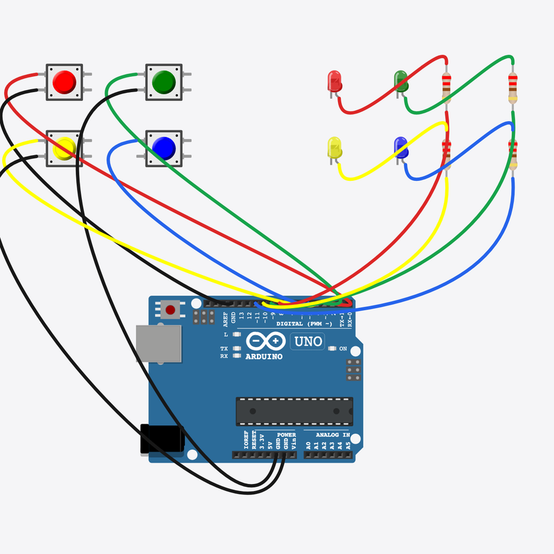
Pin connections
| Part 1 | Part 2 | |
|---|---|---|
Arduino pin 2 | → | Red button pin 1 |
Red button pin 2 | → | Arduino GND |
Arduino pin 3 | → | Green button pin 1 |
Green button pin 2 | → | Arduino GND |
Arduino pin 4 | → | Yellow button pin 1 |
Yellow button pin 2 | → | Arduino GND |
Arduino pin 5 | → | Blue button pin 1 |
Blue button pin 2 | → | Arduino GND |
Arduino pin 8 | → | Red resistor pin 2 |
Red resistor pin 1 | → | Red LED anode (+) |
Red LED cathode (-) | → | Arduino GND |
Arduino pin 9 | → | Green resistor pin 2 |
Green resistor pin 1 | → | Green LED anode (+) |
Green LED cathode (-) | → | Arduino GND |
Arduino pin 10 | → | Yellow resistor pin 2 |
Yellow resistor pin 1 | → | Yellow LED anode (+) |
Yellow LED cathode (-) | → | Arduino GND |
Arduino pin 11 | → | Blue resistor pin 2 |
Blue resistor pin 1 | → | Blue LED anode (+) |
Blue LED cathode (-) | → | Arduino GND |
Repeat the growing pattern!
Watch the LED sequence, then press matching buttons — one step longer each round.
Memory games train pattern matching — same idea as Simon toys.
The problem
You must compare each input to a stored sequence step by step.
Think of it like
Like “Simon says” — copy the pattern or you are out.
Runs your sketch
Arduino
Brain
Matches red in the sequence
Red button
Input
Matches green in the sequence
Green button
Input
Matches yellow in the sequence
Yellow button
Input
Matches blue in the sequence
Blue button
Input
Shows red in the pattern
Red LED
Output
Shows green in the pattern
Green LED
Output
Shows yellow in the pattern
Yellow LED
Output
Shows blue in the pattern
Blue LED
Output
Protects red LED
Red resistor
Safety
Protects green LED
Green resistor
Safety
Protects yellow LED
Yellow resistor
Safety
Protects blue LED
Blue resistor
Safety
Play sequence
Flashes LEDs in order from the sequence[] array.
showSequence();
Read your button
Each press maps to an index 0–3 matching an LED color.
digitalRead(BTN_PINS[i]) == LOW
Compare step
Wrong button triggers fail; correct adds another random step.
if (i != sequence[step]) failPattern();
Then loop back to step 1
Follow these steps in order. Match the wires to the colors shown.
Place Arduino
Place the Arduino (uno) on the breadboard.
Arduino placed!
Place Red button
Place the Red button (btn0) on the breadboard.
Place Green button
Place the Green button (btn1) on the breadboard.
Place Yellow button
Place the Yellow button (btn2) on the breadboard.
Place Blue button
Place the Blue button (btn3) on the breadboard.
Place Red LED
Place the Red LED (led0) on the breadboard.
Place Green LED
Place the Green LED (led1) on the breadboard.
Place Yellow LED
Place the Yellow LED (led2) on the breadboard.
Place Blue LED
Place the Blue LED (led3) on the breadboard.
Place Red resistor
Place the Red resistor (r0) on the breadboard.
Place Green resistor
Place the Green resistor (r1) on the breadboard.
Place Yellow resistor
Place the Yellow resistor (r2) on the breadboard.
Place Blue resistor
Place the Blue resistor (r3) on the breadboard.
Connect Arduino pin 2 to Red button (btn0) 1.l
Connect Arduino pin 2 to Red button (btn0) 1.l.
Connect Red button (btn0) 2.l to Arduino GND
Connect Red button (btn0) 2.l to Arduino GND.
Connect Arduino pin 3 to Green button (btn1) 1.l
Connect Arduino pin 3 to Green button (btn1) 1.l.
Connect Green button (btn1) 2.l to Arduino GND
Connect Green button (btn1) 2.l to Arduino GND.
Connect Arduino pin 4 to Yellow button (btn2) 1.l
Connect Arduino pin 4 to Yellow button (btn2) 1.l.
Connect Yellow button (btn2) 2.l to Arduino GND
Connect Yellow button (btn2) 2.l to Arduino GND.
Connect Arduino pin 5 to Blue button (btn3) 1.l
Connect Arduino pin 5 to Blue button (btn3) 1.l.
Connect Blue button (btn3) 2.l to Arduino GND
Connect Blue button (btn3) 2.l to Arduino GND.
Connect Arduino pin 8 to Red resistor (r0) 2
Connect Arduino pin 8 to Red resistor (r0) 2.
Connect Red resistor (r0) 1 to Red LED (led0) anode (+)
Connect Red resistor (r0) 1 to Red LED (led0) anode (+).
Connect Red LED (led0) cathode (-) to Arduino GND
Connect Red LED (led0) cathode (-) to Arduino GND.
Connect Arduino pin 9 to Green resistor (r1) 2
Connect Arduino pin 9 to Green resistor (r1) 2.
Connect Green resistor (r1) 1 to Green LED (led1) anode (+)
Connect Green resistor (r1) 1 to Green LED (led1) anode (+).
Connect Green LED (led1) cathode (-) to Arduino GND
Connect Green LED (led1) cathode (-) to Arduino GND.
Connect Arduino pin 10 to Yellow resistor (r2) 2
Connect Arduino pin 10 to Yellow resistor (r2) 2.
Connect Yellow resistor (r2) 1 to Yellow LED (led2) anode (+)
Connect Yellow resistor (r2) 1 to Yellow LED (led2) anode (+).
Connect Yellow LED (led2) cathode (-) to Arduino GND
Connect Yellow LED (led2) cathode (-) to Arduino GND.
Connect Arduino pin 11 to Blue resistor (r3) 2
Connect Arduino pin 11 to Blue resistor (r3) 2.
Connect Blue resistor (r3) 1 to Blue LED (led3) anode (+)
Connect Blue resistor (r3) 1 to Blue LED (led3) anode (+).
Connect Blue LED (led3) cathode (-) to Arduino GND
Connect Blue LED (led3) cathode (-) to Arduino GND.
Sequence storage
const int BTN_PINS[] = {2, 3, 4, 5};
const int LED_PINS[] = {8, 9, 10, 11};
const int NUM = 4;
const int MAX_LEN = 6;
int sequence[MAX_LEN];
int seqLen = 1;
int step = 0;
enum Phase { SHOW, INPUT };
Phase phase = SHOW;
sequence[] holds the pattern; seqLen grows as you succeed.
showSequence()
void showSequence() {
  for (int i = 0; i < seqLen; i++) {
    flash(sequence[i], 350);
    delay(180);
  }
}
Plays each stored index by flashing the matching LED.
Input compare
void loop() {
  if (phase == SHOW) {
    showSequence();
    step = 0;
    phase = INPUT;
    return;
  }
  for (int i = 0; i < NUM; i++) {
    if (digitalRead(BTN_PINS[i]) == LOW) {
      delay(180);
      flash(i, 250);
      if (i != sequence[step]) {
        failPattern();
        return;
      }
      step++;
      if (step >= seqLen) {
        seqLen++;
        if (seqLen > MAX_LEN) {
          seqLen = MAX_LEN;
        }
        sequence[seqLen - 1] = random(0, NUM);
        phase = SHOW;
      }
      while (digitalRead(BTN_PINS[i]) == LOW) {
        delay(10);
      }
    }
  }
  delay(20);
}
INPUT phase checks each press against sequence[step] — core Simon logic.
const int BTN_PINS[] = {2, 3, 4, 5};
const int LED_PINS[] = {8, 9, 10, 11};
const int NUM = 4;
const int MAX_LEN = 6;
int sequence[MAX_LEN];
int seqLen = 1;
int step = 0;
enum Phase { SHOW, INPUT };
Phase phase = SHOW;
void flash(int idx, int ms) {
  digitalWrite(LED_PINS[idx], HIGH);
  delay(ms);
  digitalWrite(LED_PINS[idx], LOW);
  delay(120);
}
void showSequence() {
  for (int i = 0; i < seqLen; i++) {
    flash(sequence[i], 350);
    delay(180);
  }
}
void failPattern() {
  for (int blink = 0; blink < 3; blink++) {
    for (int i = 0; i < NUM; i++) {
      digitalWrite(LED_PINS[i], HIGH);
    }
    delay(200);
    for (int i = 0; i < NUM; i++) {
      digitalWrite(LED_PINS[i], LOW);
    }
    delay(200);
  }
  seqLen = 1;
  sequence[0] = random(0, NUM);
  phase = SHOW;
}
void setup() {
  for (int i = 0; i < NUM; i++) {
    pinMode(BTN_PINS[i], INPUT_PULLUP);
    pinMode(LED_PINS[i], OUTPUT);
  }
  randomSeed(analogRead(0));
  sequence[0] = random(0, NUM);
}
void loop() {
  if (phase == SHOW) {
    showSequence();
    step = 0;
    phase = INPUT;
    return;
  }
  for (int i = 0; i < NUM; i++) {
    if (digitalRead(BTN_PINS[i]) == LOW) {
      delay(180);
      flash(i, 250);
      if (i != sequence[step]) {
        failPattern();
        return;
      }
      step++;
      if (step >= seqLen) {
        seqLen++;
        if (seqLen > MAX_LEN) {
          seqLen = MAX_LEN;
        }
        sequence[seqLen - 1] = random(0, NUM);
        phase = SHOW;
      }
      while (digitalRead(BTN_PINS[i]) == LOW) {
        delay(10);
      }
    }
  }
  delay(20);
}
Q1. Where does repeating work belong?
Q2. What happens when you press the wrong button?
Slow the show — change flash delay 350 to 500 in showSequence (inside flash call line 18).
Hint: Line 18.
Comment line 56 explaining wrong button check.
Hint: if (i != sequence[step])
A line-by-line tour of the sketch — the same steps as in Robo Gurukul Studio.
Program overview
Technical
Sketches have globals, then setup() once, then loop() forever.
In this project
Watch a growing LED sequence, then repeat it with matching buttons.
Why here
Read from top to bottom. Hover words or lines for help!
const int BTN_PINS[] = {2, 3, 4, 5};
const int LED_PINS[] = {8, 9, 10, 11};
const int NUM = 4;
const int MAX_LEN = 6;
int sequence[MAX_LEN];
int seqLen = 1;
int step = 0;
enum Phase { SHOW, INPUT };
Phase phase = SHOW;
void flash(int idx, int ms) {
  digitalWrite(LED_PINS[idx], HIGH);
  delay(ms);
  digitalWrite(LED_PINS[idx], LOW);
  delay(120);
}
void showSequence() {
  for (int i = 0; i < seqLen; i++) {
    flash(sequence[i], 350);
    delay(180);
  }
}
void failPattern() {
  for (int blink = 0; blink < 3; blink++) {
    for (int i = 0; i < NUM; i++) {
      digitalWrite(LED_PINS[i], HIGH);
    }
    delay(200);
    for (int i = 0; i < NUM; i++) {
      digitalWrite(LED_PINS[i], LOW);
    }
    delay(200);
  }
  seqLen = 1;
  sequence[0] = random(0, NUM);
  phase = SHOW;
}
setup()
Technical
Runs one time when the board turns on.
In this project
Sets up pins and libraries for Simon Says.
Why here
One-time setup belongs here—not in loop().
void setup() {
  for (int i = 0; i < NUM; i++) {
    pinMode(BTN_PINS[i], INPUT_PULLUP);
    pinMode(LED_PINS[i], OUTPUT);
  }
  randomSeed(analogRead(0));
  sequence[0] = random(0, NUM);
}
loop()
Technical
Runs again and again after setup() is done.
In this project
This is the main action you see in Simon Says.
Why here
Repeating work (blink, read sensors) goes here.
void loop() {
  if (phase == SHOW) {
    showSequence();
    step = 0;
    phase = INPUT;
    return;
  }
  for (int i = 0; i < NUM; i++) {
    if (digitalRead(BTN_PINS[i]) == LOW) {
      delay(180);
      flash(i, 250);
      if (i != sequence[step]) {
        failPattern();
        return;
      }
      step++;
      if (step >= seqLen) {
        seqLen++;
        if (seqLen > MAX_LEN) {
          seqLen = MAX_LEN;
        }
        sequence[seqLen - 1] = random(0, NUM);
        phase = SHOW;
      }
      while (digitalRead(BTN_PINS[i]) == LOW) {
        delay(10);
      }
    }
  }
  delay(20);
}
Try this: Change numbers in loop(), then compile and run the simulator.
pinMode
Technical
Tells a pin if it listens or drives something.
In this project
Gets the Simon Says circuit ready in the simulator.
Why here
Goes in setup() because we only set pins once at the start.
pinMode(BTN_PINS[i], INPUT_PULLUP);
digitalWrite
Technical
Turns a pin ON or OFF.
In this project
Controls lights, motors, or buzzers in Simon Says.
Why here
Goes in loop() so it can keep changing while the program runs.
digitalWrite(LED_PINS[idx], HIGH);
digitalRead
Technical
Checks if a pin is ON or OFF.
In this project
Reads buttons or sensors in Simon Says.
Why here
Goes in loop() so we can react when something changes.
if (digitalRead(BTN_PINS[i]) == LOW) {analogRead
Technical
Reads a sensor number from 0 to 1023.
In this project
Turns a sensor signal into a number for Simon Says.
Why here
Goes in loop() to keep checking the sensor.
randomSeed(analogRead(0));
delay
Technical
Waits for some time. Nothing else runs during the wait.
In this project
Controls speed so you can see Simon Says in the simulator.
Why here
Right after an action that should stay the same for a moment.
delay(ms);
random
Technical
Picks a random number in a range.
In this project
Adds randomness in Simon Says.
Why here
In loop() when you want different values each time.
sequence[0] = random(0, NUM);